So, you’re obviously curious about the methodology we use in order to provide more realistic repeater coordination and thereby give more Amateur Radio repeater enthusiasts in Alabama the ability to put repeaters into operation while avoiding harmful interference between repeaters. This article shows you how we achieve this.
[Note: you can click on any of the images in this article to open a larger view.]
Let’s start by creating a hypothetical repeater. Let’s give it the following operating parameters:
- Repeater name: Repeater “A”
- Location: Ft. Deposit, AL
- Operating band: 2 Meters
- Operating frequency: 146.820 MHz output with a 146.220 MHz input
- Operating mode: Analog FM wideband (WFM)
- PL Tone (CTCSS) frequency: 123.0 Hz
- Antenna height above ground level (AGL): 144.78 Meters (475′)
- Effective radiated power after feedline losses, antenna gain, etc.: 115 Watts
Now, let’s say someone is applying to put a repeater into operation in New Site, AL. Let’s give it a designation of Repeater “B.” Let’s also assume that using a list of the existing repeaters in Alabama and Georgia, the greatest
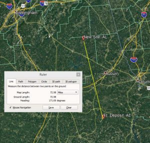
distance from the desired location for Repeater “B” to be separated from another repeater using an agreed upon list of repeater pairs (i.e., “band plan” or “frequency utilization plan”) is 73 miles. It’s 73 miles from Repeater “A” operating at 146.820 (-) 123.0 PL tone.
Here are the operating parameters for proposed Repeater “B:”
- Repeater name: Repeater “B”
- Location: New Site, AL
- Operating band: 2 Meters
- Operating frequency: 146.820 MHz output with a 146.220 MHz input
- Operating mode: Analog FM wideband (WFM)
- PL Tone (CTCSS) frequency: 167.9 Hz
- Antenna height above ground level (AGL): 100.0 Meters (238′)
- Effective radiated power after feedline losses, antenna gain, etc.: 150 Watts
Under the old “100 mile separation” methodology, the applicant for Repeater “B” (the proposed new repeater) would have gotten a simple answer of “No” in response to his application. The long outdated “100 mile” rule made the job pretty easy for the person doing the frequency coordination — how much time and energy does it take to say “No,” right? Well, apparently it often did take a while in many cases and was overly taxing work, as we’ve heard countless stories of Alabama hams applying and then waiting… and emailing… and waiting… and calling… and waiting… only to eventually be told “No.”
There is a reason such simplified methodology and rules are not used in other areas of repeater and radio services such as public safety, business, and other critical services: such overly-simplified rules don’t make effective, efficient, and realistic use of limited RF space. Now let us apply the same methods used in those other services — truly critical services — and see how it helps us do a better job of frequency coordination and makes it possible for more repeaters to be coordinated and coexist using the same frequency pairs.
In order to determine more realistically what area a given repeater will cover reliably (and what area of operation should be “protected,” so to speak, through coordination) involves looking at many parameters — not just its distance from other repeaters. Simply saying “all other repeaters on the same frequency have to be at least 100 miles away” (or some other distance, based on operating band) assumes that the repeater — and all repeaters — operating on a given frequency will have exactly the same coverage distance and area. If you have been a ham more than a few hours, you’ve probably already learned that many factors — transmitter power, antenna height, antenna gain, antenna pattern, feedline losses, effective radiated power, terrain and topography (site elevation above average terrain, hills, mountains, valleys, etc.) all have tremendous influence on how much coverage area a repeater will actually cover reliably. Since every individual repeater has its own unique set of values for all these parameters, it is obvious that basing repeater separation on nothing but the distance between them without taking the other factors into account is actually unrealistic, inefficient, and prohibits many hams from being able to put a coordinated repeater into operation.
The tools are more readily available than ever in history to calculate and plot (map) a more realistic picture of a repeater’s coverage abilities. By employing the FCC prescribed methodology which is used in the Land Mobile Radio (LMR) services, we can now easily plug the numbers for a repeater into a computer and determine two extremely useful parameters defined by the FCC:
- Service Contour
- Interference Contour
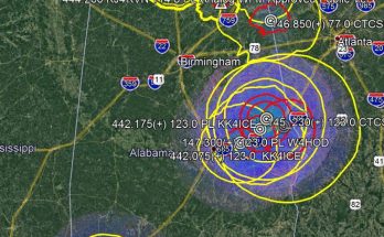
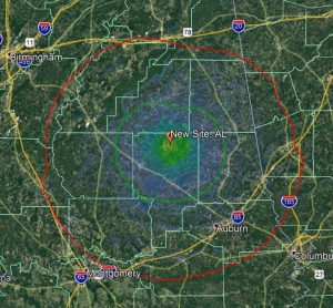
To demonstrate, let us use our hypothetical, coordinated Repeater “A” located in Ft. Deposit, AL and generate and plot/map those two contours and discuss their meaning and significance. In image 2, you can see that after crunching the numbers, two rough circles have been generated and mapped. The green, innermost circle is the
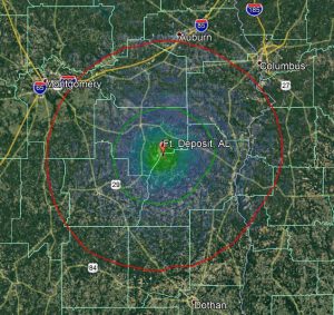
“Service Contour.” The Service Contour is the area inside of which the repeater is expected to produce a given minimum signal for a certain minimum percentage of receivers with a specified sensitivity and an antenna at a certain height, etc. a certain minimal percentage of the time. Sounds like a mouthful, but in a nutshell it means the area inside the green perimeter (the Service Contour) is the area where the repeater can be expected to work quite well for mobiles on a pretty consistent basis.
The area between the green Service Contour and red “Interference Contour” is another matter. Quite simply, the ability of mobile or handheld radios to be able to access and actually hear the repeater reliably becomes much more “iffy.” As you move farther away from the repeater and closer to the Interference Contour, it becomes more and more likely that the repeater won’t work well for you, in which case you simply discontinue your QSO, turn around and drive closer to the repeater or find a hilltop, etc. (if your QSO is really that critical), move the QSO to another repeater, grab your cellphone and just call the other person… whatever. With these two contour circles established and mapped for Repeater “A” in mind, let us jump over and do the same thing for proposed Repeater “B.”
While proposed Repeater “B” would operate on the same frequency pair as Repeater “A,” it has its own output power level, antenna height, site elevation, terrain and topography at and around the site, etc. Even if we kept all factors such as transmitter power, feedline losses, duplexer and connector losses, antenna type, antenna gain, antenna pattern, etc. exactly the same as Repeater “B,” the coverage area could still be significantly different. If the site of Repeater “A” is in a valley surrounded by hills, it would have much less coverage than it would if the site were atop a high hill or mountain. The same holds true for Repeater “A.” The Service and Interference Contours for a repeater are calculated taking all of that and more into account.
The next logical step in improved frequency coordination is to look at the Service and Interference Contours of both the existing repeater (“A”) and the proposed repeater (“B”) at the same time. Image 4 shows that. When we plot both on the map simultaneously, what we discover is that the Service Contours
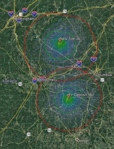
for the two repeaters (their most reliable coverage areas) would not overlap. They don’t even come close. In fact, the closest distance between their service contours is about 35 miles. That means there is at least a 35 mile distance between the two repeaters where the ability of a mobile radio to be able to reliably use either one can be expected to be hit-or-miss. A mobile or handheld radio in that 35 mile area might not be able to hit either repeater well or consistently. Factor in something we haven’t even mentioned before — having a different CTCSS or DCS squelch tone on the input of each of the two repeaters — would mean that a mobile trying to hit one of the repeaters would not key up the other repeater anyway. For even better operation, the repeater owners can also use CTCSS or DCS on the outputs of the repeaters, in which case users of the repeaters could use the receive CTCSS/DCS feature on their radios, and we start realizing even more that the old, simplified methods of repeater coordination wasted a lot of spectrum and repeater real estate. Yes, it was easier for frequency coordinators to just say “No” and refuse to help a ham get a repeater on the air, but with the tools we have readily available to us today, the old mileage rules simply do not stand up to 21st Century level standards or scrutiny.
Once we have the Service and Interference Contours mapped for both repeaters, how do we actually decide whether or not Repeater “B” should receive coordinated status and be recommended for operation? Drawing upon the FCC’s LMR rules and methodology again, it becomes pretty simple. In LMR, the rules state that the Service Contours of two repeaters/transmitters operating on the same frequency must not overlap. They also state the Interference Contour of a repeater/transmitter is not allowed to overlap the Service Contour of another repeater/transmitter operating on the same frequency. Looking at our example case, we can see that while the Interference Contours of the two repeaters have a relatively small area where they overlap, neither of the repeaters’ Interference Contours overlaps the Service Contour of the other repeater. With the exception of the occasional, temporary “band opening” or other events likely to occur only on rare occasions, these two repeaters should be able to coexist quite nicely, especially given that the two repeaters would have different input and output squelch tones/codes. In fact, these two repeaters could be coordinated another 12 miles or so closer to one another and still coexist as good neighbors in the ham world.
Let’s look at another situation in which simple “separation by a certain distance in miles” don’t work well: the situation of a “super repeater.” What some of us refer to as “super repeaters” are repeaters operating with some combination extreme antenna height (like antennas atop 1,500+ towers (we should all be so lucky, huh?)), repeaters atop high mountains, repeaters with high-gain, directional pattern antennas which can really “reach out there” in certain directions while by comparison being deaf as a post in other directions, etc. Some of these repeaters might have Service Contours which extend out a great distance in some or all directions. It was very difficult — if not practically impossible — for most frequency coordinators in the past to do the extensive calculations and mapping necessary to create specialized, detailed, useful coverage maps for such repeaters. In all fairness, it would have been unrealistic to ask or expect them to do so, especially since frequency coordination for Amateur Radio is done on a volunteer basis. But the technology and tools have easily been within the reach of frequency coordinators for many years now to employ LMR Contour methodology — and they are getting more plentiful, less expensive, more reliable, and easier to use. If it was good enough for LMR repeater coordination (and it has proven to work very well for many years), it is not only good enough for Amateur radio repeaters — we see it as a quantum leap forward in coordination methodology.
Now that you have seen one of the big differences in our coordination methodology (and hopefully we’ve presented it clearly enough that it makes sense), you can clearly see how AFCRAS is embracing 21st Century technology and thinking in order to provide Alabama Amateur Radio licensees and enthusiasts the kind of services you deserve and have vehemently stated a desire for.
To summarize our use of LMR Contour methodology:
- We generate and map the Service Contour and Interference Contour for a proposed repeater.
- We generate and map the Service Contour and Interference Contour for existing repeaters using the same frequencies within certain a given distance of the proposed repeater (a distance which is actually greater than the distance used in the antiquated “separation by distance only” rules most other frequency coordinators still use today.
- If the following conditions are met, we will proceed with the coordination process for the proposed repeater:
- The Interference Contour of the proposed repeater must not overlap the Service Contour(s) of any existing repeater(s) operating on the same input and/or output frequencies within the specified Coordination Clearance Perimeter (CCP).
- The interference Contours of existing repeater(s) within the operating on the same input and/or output frequency which are located within the CCP of the proposed repeater must not overlap the Service Contour of the proposed repeater.
- CTCSS frequency/DCS squelch tone for the proposed repeater must not be the same as the CTCSS/DCS for any existing repeater(s) using the same input and/or output frequencies within the specified CCP of the site of the proposed repeater.
- If the above three conditions are not met, then coordination will not proceed without the applicant agreeing to modify his/her application in order for it to meet meet the Contour overlap and CTCSS/DCS requirements. There are also provisions in the AFCRAS CPG which allow for the owner(s) of the existing, coordinated repeater(s) involved to agree to modify their coordination and operating parameters. Refer to the AFCRAS CPG for more in-depth information regarding that option and AFCRAS repeater coordination in general.
73, and you’re most welcome 😉